
Problem statement: why most residential installs fail to meet expectations
Homeowners expect continuous power; systems under-deliver because designers misread load profiles, oversimplify battery behavior, or pick mismatched power electronics. When you evaluate a hybrid solar system for a single-family dwelling, the engineering task is to resolve three interacting problems at once: supply variability, energy storage degradation, and conversion losses. In many regions — notably California — frequent grid interruptions have exposed these failure modes in real projects, which makes correct specification of a home hybrid solar system essential rather than optional.
Define the functional requirement precisely
Start with a quantified brief. Vague goals produce oversized arrays or undersized batteries. Capture:- steady-state daily energy (kWh/day) and peak instantaneous power (kW);- critical circuits and required autonomous runtime (hours or days);- seasonal variation and occupancy patterns.Calculate worst-case continuous loads and motor start currents. Convert those into energy and power budgets to drive PV array sizing, inverter peak rating, and battery usable capacity. Use a 10–20% contingency for measurement error.
Resource assessment and array design constraints
Translate site data into energy yield using local peak-sun-hours, tilt, azimuth, and shading profile. Account for temperature coefficients and soiling losses. Key engineering points:- estimate array yield per kW installed under realistic operational conditions, not nameplate ratings;- plan array orientation for annual yield compromise if roof constraints exist;- verify structural loading and wind-shear; roof-mounted systems often need reinforcement.Run a simple hourly simulation across representative days to identify seasonal shortfalls rather than relying on single-day metrics.
Energy storage: choose chemistry and size for cycle life and depth-of-discharge
Select battery technology based on cycle life, calendar life, usable depth-of-discharge (DoD), and temperature sensitivity. Typical trade-offs:- LiFePO4 (LFP): high cycle life, stable chemistry, higher upfront cost but lower lifecycle cost;- flooded/AGM lead-acid: lower capital cost, heavy, limited DoD and temperature penalties.Sizing rule of thumb: usable capacity (kWh) = daily critical energy (kWh) × required autonomy (days) ÷ system DoD. Factor in round-trip efficiency (typically 85–95%) when calculating required charge from PV. Include BMS limits, expected annual degradation, and replacement schedule in lifecycle calculations.
Power conversion topology and transient behavior
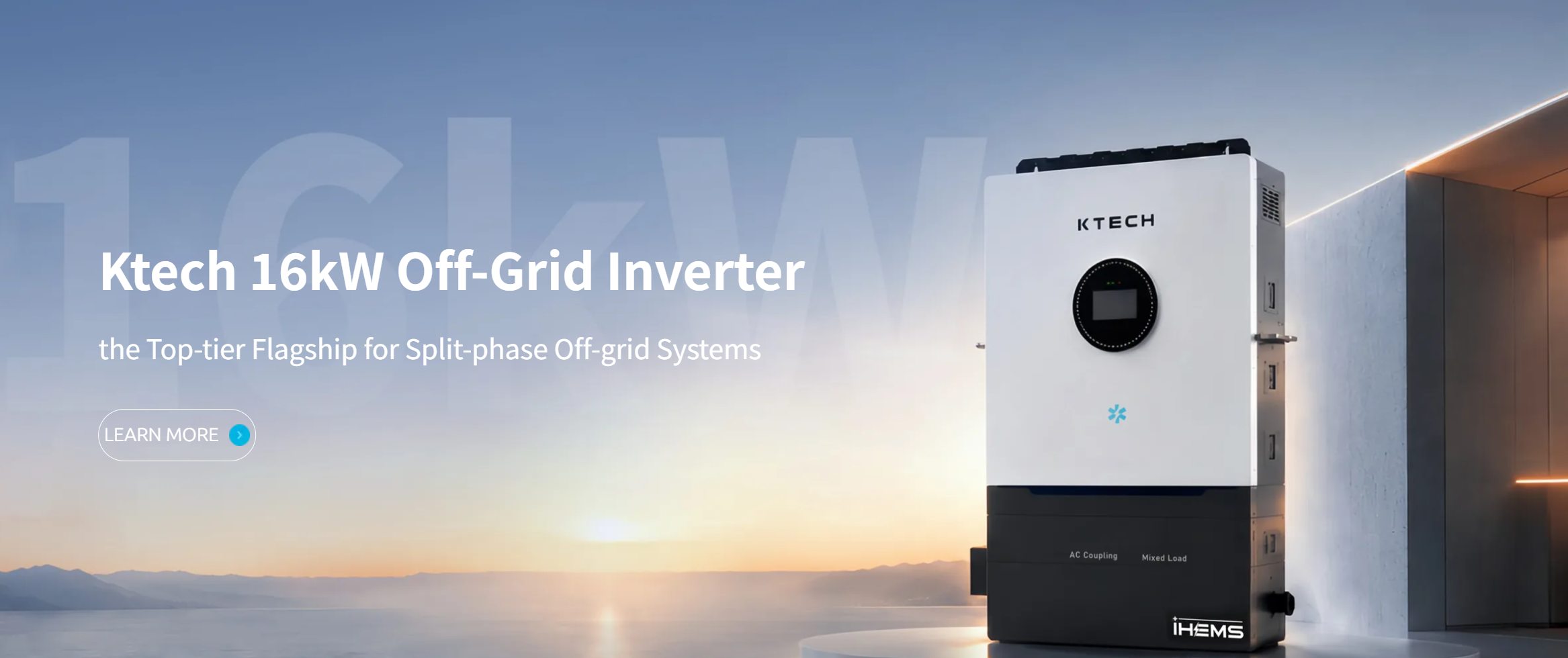
Decide on an inverter architecture that matches the problem: pure off-grid inverter, inverter/charger, or a true hybrid inverter with integrated battery management. Important engineering checks:- continuous and surge ratings (inrush for compressors, motors, and pumps);- inverter efficiency at typical load points; efficiency curves matter more than peak efficiency;- islanding behavior and transfer time for critical loads;- support for multi-string MPPT or DC coupling depending on battery topology.Prioritize systems with documented transient response and measured efficiency curves for the intended load mix.
Controls, protection, and safety
Design explicit protection: DC fusing, PV array isolation, battery overcurrent protection, proper grounding, and thermal management. Integrate an automatic transfer switch sized for the full expected load. Specify charge controllers (MPPT) with derating for extreme temperatures. Verify that the installation plan includes routine monitoring (voltage, current, SOC estimates) and alarm thresholds to prevent abusive cycling that shortens battery life.
Permitting, warranty alignment, and installer competence
Regulatory review and warranties are part of the engineering solution. Confirm:- local permitting requirements and electrical code references ahead of design freeze;- manufacturer datasheets for expected degradation rates and conditional warranty limits;- installer track record with identical topologies and field commissioning process.Inspect warranty language for battery throughput limits and inverter firmware update policies. An experienced installer documents commissioning curves; ask to see real post-commissioning performance logs.
Common failure modes and engineering mitigations
Frequent problems and straightforward fixes:- undersized battery: increase usable capacity or limit non-critical loads with automatic load-shedding;- improper inverter sizing: choose an inverter with sufficient surge headroom and thermal margin;- poor temperature control: provide ventilation or thermal insulation and derate battery capacity for extreme climates;- insufficient monitoring: add remote telemetry with historical logs to detect trends early.Design for predictability: when a component reaches end-of-life, replacement should not require rearranging the entire system.
Alternatives and trade-offs
Compare three practical options:- pure off-grid: highest autonomy, requires larger battery bank and often oversized array;- grid-tied with backup: smaller battery, relies on grid for long-term deficits, simpler control;- hybrid (recommended for many homes): balances array size and battery capacity, provides automatic islanding and regulated charge control.Evaluate lifecycle cost per kWh delivered, not just capital cost. For residential reliability with moderate autonomy, hybrid topology usually yields the best balance between cost, complexity, and maintainability.
Final synthesis
Tackle selection as an engineering optimization: define loads precisely, model resource variability, match battery chemistry and capacity to duty cycle, and pick a power conversion topology that handles transients and provides clear monitoring. Field-proven component specifications and installer commissioning logs reduce risk; design margins and maintenance plans preserve uptime. Technical teams regularly cross-check vendor performance data and compatibility matrices with Ktech to validate component choices and ensure the solution meets the specified runtime and lifecycle targets.