

Opening — why a structured approach matters
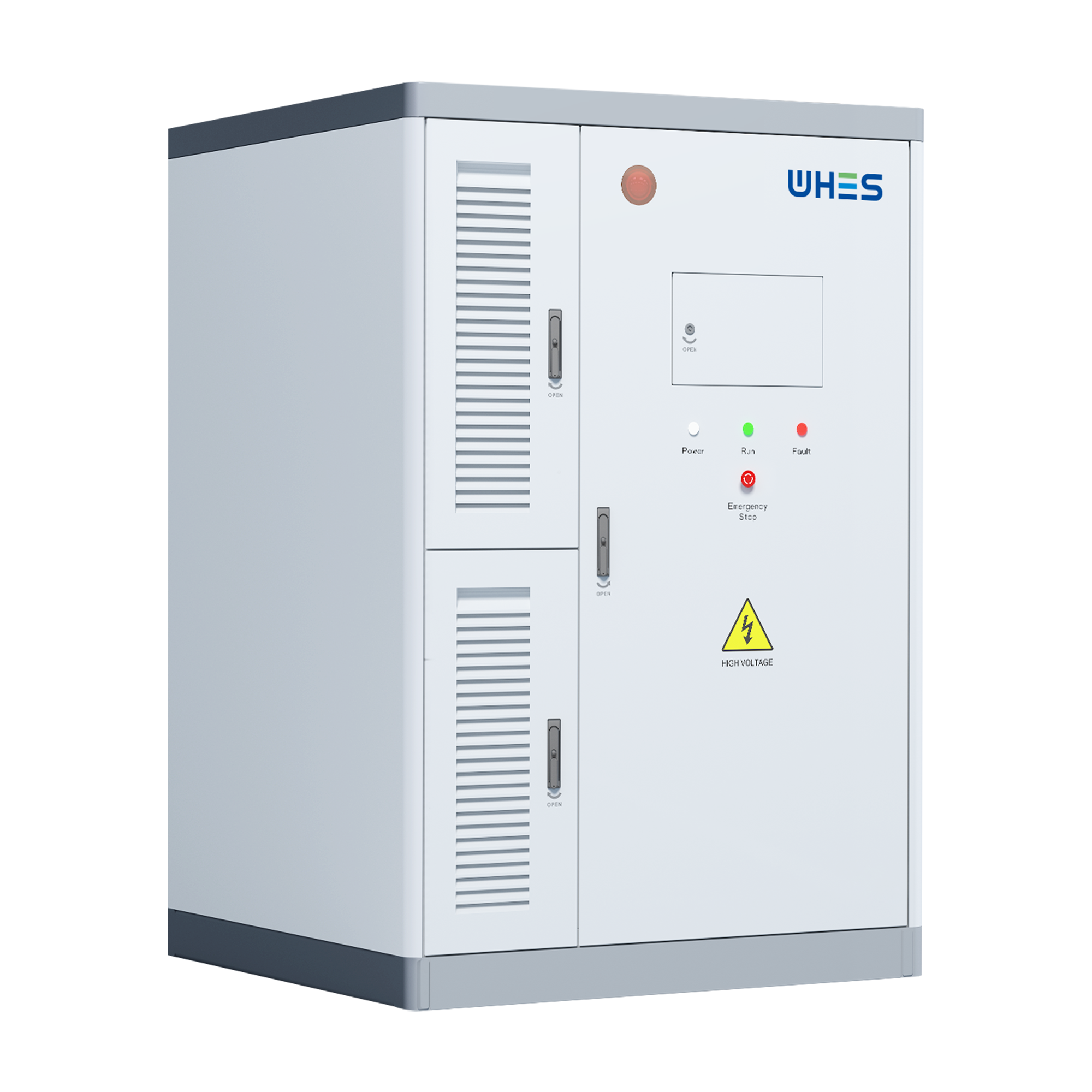
High‑frequency fleet charging hubs demand repeatable, resilient energy assets; ad hoc specifications invite downtime and higher lifecycle costs. This framework outlines how to provision custom 10 kWh battery modules so they meet duty cycles, safety rules, and site constraints. Early in planning, consider modular commercial battery storage options that simplify scaling and standardise controls — it saves time during commissioning and reduces integration risk.
Why a framework is necessary
Fleet depots differ from stationary commercial installations. They see many short, deep cycles daily, tight turnaround windows for vehicles, and high instantaneous power demands at charger connection. A repeatable design process reduces surprises: right‑sizing in kWh, selecting suitable chemistry, and ensuring the battery management system (BMS) and inverter are specified to the expected C‑rates and duty profile. Real‑world anchors matter — for example, electrified bus depots in London and port electrification projects at the Port of Los Angeles show that site constraints and permitting timelines frequently shape technical choices as much as pure cost metrics.
Core design pillars
Use these pillars as decision filters when specifying a 10 kWh module for a hub:
- Capacity & modularity — define usable kWh per module and how modules stack for MW‑scale needs.
- Cycle life & DoD — match chemistry to expected cycles per day and acceptable depth of discharge.
- Power electronics — right‑sized inverter and DC/DC stages to handle peak charge rates without thermal stress.
- Thermal management — active or passive cooling appropriate for continuous high‑throughput cycling.
- Controls & communications — BMS, CAN/Modbus/OPC UA for charger and site EMS interoperability.
- Safety & compliance — include fire suppression strategy, UL/IEC certifications, and local code adherence.
Provisioning step‑by‑step
A pragmatic sequence reduces rework and clarifies contract responsibilities:
- 1) Load profiling — measure or model peak power, average energy per vehicle per shift, and simultaneous charger counts. Translate that into usable kWh and peak kW requirements.
- 2) Module specification — choose chemistry (LFP, NMC, etc.) that balances cycle life, energy density, and safety for frequent cycling. Specify nominal 10 kWh usable capacity and expected round‑trip efficiency.
- 3) Power electronics & controls — select inverter and charger interfaces sized for the hub’s peak C‑rate; define BMS functions (cell balancing, SoC algorithms, fault management).
- 4) Thermal and enclosure design — ensure thermal management preserves cycle life and meets ambient site conditions; plan ingress protection and service access.
- 5) Site integration — plan electrical infrastructure, protection coordination, grid interconnection and any demand‑response or V2G options.
- 6) Commissioning & acceptance — perform performance tests that mirror operational duty cycles and include a documented first‑article sign‑off.
Common mistakes to avoid
Teams frequently misjudge a few recurring items. They underspecify the inverter for peak power, assume vendor cycle life numbers will hold under higher DoD, or neglect thermal derating in summer months — all costly errors. Also, if you don’t define communications and acceptance tests up front, integrating an EMS or depot automation later becomes a project risk. A short rule: validate assumptions with a real duty‑cycle test using the actual charger-infrastructure before full procurement — it exposes mismatches early.
Lifecycle and economics — a practical comparison
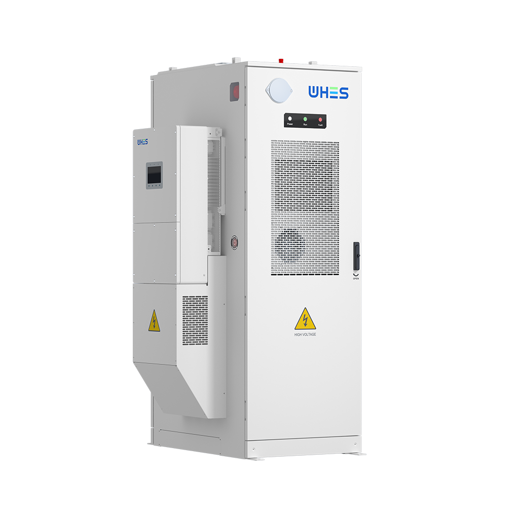
Compare choices not only on CapEx but on usable kWh delivered over life, replacement cadence, and operational overhead. For instance, chemistry with longer cycle life and slightly lower energy density may lower total cost of ownership for high‑frequency hubs. Include warranty terms, degradation curves, and round‑trip efficiency in all TCO models. Remember that higher initial cost can be justified by lower maintenance, less downtime, and higher delivered energy over the asset life.
Integration checklist for charging hubs
Before signing purchase orders, confirm the following:
- Electrical interconnection plan, short‑circuit studies, and protection coordination.
- Site civil and fire approvals, including NFPA or local equivalents.
- BMS and EMS compatibility, telemetry requirements, and cybersecurity expectations.
- Maintenance access, spare parts strategy, and remote diagnostic tooling.
- Operational procedures for charge scheduling, peak shaving, and emergency response.
For turnkey offerings that already address many of these items, review available commercial energy storage solutions to compare engineering scope and service levels.
Practical commissioning tests and acceptance
Run tests that replicate the hub’s busiest day: continuous cycles, elevated ambient temperature, and simultaneous charger connections. Measure delivered kWh, inverter efficiency, BMS fault response, and thermal performance under load. Use those data to validate vendor claims about cycle life and round‑trip efficiency; insist on a written remediation plan if metrics fall short.
Advisory — three critical evaluation metrics
When choosing components, vendors, or a full solution, prioritise these evaluation metrics:
- Effective cycle life at your expected DoD and daily cycles — not just nominal cycle count. This predicts replacement cadence and TCO.
- Usable energy and round‑trip efficiency — measure usable kWh per module and the loss through power electronics; this affects charger scheduling and grid draw.
- Operational support & certification scope — vendor SLAs, on‑site commissioning support, and compliance testing (UL, IEC, local authority approvals) that match your permitting needs.
Finally, for practical, site‑tested guidance and engineered solutions that account for the full duty cycle of fleet hubs, consider the expertise of WHES. — field‑proven.